Miscellaneous research projects and interests
Parametric acoustic array
Traditional loudspeakers provide an efficient means of transmitting sound over a wide area and over a wide range of frequencies. The larger diameter the loudspeaker, the lower the frequencies of sound which can be generated.
These loudspeakers are generally omni-directional at lower frequencies, and although they exhibit directionality at higher frequencies, they still disperse noise over a wide area. As an illustration, consider the sound radiated by a baffled piston vibrating harmonically.
The animation shows the sound pressure and directivity of a piston vibrating against a flat wall, similar to a loudspeaker. At low frequencies the sound pressure is low but omnidirectional (no control over where the sound propagates). As the excitation frequency increases, the piston becomes a more efficient radiator of sound, generating relatively high sound pressure levels but with specific directivity, with a main beam and sidelobes. The piston is 5cm radius in air with a harmonic velocity of 0.01m/s and the excitation frequency ranges from 0.5 to10 kHz. Click on the animation to see a larger picture.
This explains why loudspeaker packages include many different speaker sizes, for different frequency ranges, as no one-size produces high amplitudes in all directions at all frequencies. Instead you mix speaker sizes to optimise the sound field.
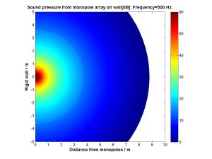
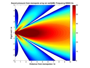
The reason why the loudspeaker is directional is that the sound from one side of the speaker cone is added to the sound from the other side, using constructive or destructive interference of the propagating sound waves. This occurs over the whole speaker surface and generates so many small differences in phase that you end up with directivity which changes with excitation frequency.
To illustrate this, examine the same rigid wall with 1600 monopoles sources (injections of mass in and out of the wall) in the same 5cm radius circular area (the monopoles are positioned with the same energy per area as the baffled piston). Even with only 40 monopoles at each angular and radial position the directivity can be seen.
If we are interested in generating lower frequencies with specific directivity, the traditional loudspeakers are not suitable. In addition, as is seen above, to generate low frequencies requires a large speaker cone. In this case we turn our attention to the ultrasonic parametric array to generate low frequency waves with specific directivity with small components.
It is possible to obtain a highly directional sound source, at lower frequencies than would be possible with a traditional speaker by using ultrasonic transducers. Researchers discovered in the 1960's that projecting two ultrasonic beams of slightly different frequencies (f1 and f1 [Hz]) caused a scattered sound field at a frequency (f1-f2 [Hz]) due to the non-linear attenuation of high amplitude sound in air or water.
Although much research was carried out, it is only relatively recently that the required portable computing power of digital signal processors (and a reduction in their cost) has enabled the real time solution of the non-linear wave equations.
This project contains research to utilise acoustic parametric arrays in modern applications, through an understanding of the physical mechanisms involved and the optimum methods to adjust both the quality of the sound projected and the directionality in real-time.
Embedded sensors in automotive tyres
The designs for both tyres and cars are incredibly competitive with manufacturers looking for methods to obtain an advantage over other brands. The information available about the tyre / road interface, including the level of grip, slip angles and footprint contact area must at present be inferred by examining the different rotation of the individual wheel hubs, through sensors mounted for the anti-lock braking system.
Although a traditionally conservative industry as safety is critical, the use of embedded sensors in tyres is becoming more acceptable, such as wireless pressure warning systems.
This project contains research which examines what real-time information on the road condition can be inferred from the vibration of the tyre surface, either measured on the tyre carcass, wheel hub or tyre sidewall, where a wireless three axis accelerometer is installed inside the air cavity. These devices are self powered using the vibration of the surface and piezo-electric crystals.
The devices yield information on the slip angles at the footprint, the grip levels available between the tyre and road surface and the pneumatic trail.
Damping of the internal tyre cavity resonance
Modern cars are developed to be quiet and comfortable as these are factors associated with luxury brands. One problem which has been particularly difficult to prevent is an acoustic resonance inside the tyre cavity, which occurs at around 250Hz. If any of the suspension components also have a natural frequency around this value, then a transmission path can be created so that the noise is heard inside the vehicle, which is particularly annoying for the owner.
Attempts to include damping material, e.g. polyurethane foam inside the cavity have not proved successful due to heat concerns, life cycle and reliability problems. The issue is also complicated by rotation of the tyre. Some potential solutions are a metal foam sprayed onto the wheel hub, Helmholtz resonator designs, use of vortex damping or traditional foam materials, however to determine the specification required, the magnitude of the loss factor must be known.
To address this, a numerical code was written based on wave propagation in waveguides, where passive resonators which rotate with the wheel assembly can be introduced. The passive resonators, including quarter-wavelength tubes and Helmholtz resonators provide sufficient attenuation over the narrow frequency range of interest. The study has demonstrated the change in natural frequency with temperature, the mode splitting due to rotation and the contact patch and the effect the change in tyre size yields. It also shows the amplitude of the loss factor required of any damping material for a certain sound pressure reduction at the hub.
Measurement of the void fraction in multiphase pipe flow through acoustic measurements and multiple microphone sensors.
Under development.
Design of variable length exhaust pipes for low-mach speed fluid flow in aeronautical and automotive applications.
Under development.