Structural vibration
At the design stage of a product, it is necessary to be able to accurately predict the natural frequencies of vibration of a complex panel, the overall loss factor and the amplitude of the response modes to excitation forcing.
In order to minimise vibration and noise, the need for novel and efficient damping methods for structural panels is still highly important. This is especially the case for products requiring very little mass addition and significant vibration reduction.
A highly efficient damping method for structural plates with low vibration amplitude characteristics uses viscoelastic damping applied to small indentations of quadratic power-law profile of the panel thickness.
As an example, the rectangular plate shown has a variation of thickness at the centre with damping applied to the tip of the profile. The surrounding material still provides significant longitudinal and torsional stiffness.
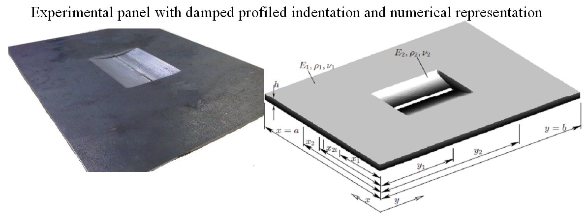
Using a damped tapered profile results in approximately double the vibration reduction compared to the traditional method of covering the whole plate with damping material yet uses between 5-10 percent of the material. It is especially effective at higher frequencies.
Traditional finite element methods and boundary element methods can have problems solving schemes where the wavenumber length scale changes dramatically in certain areas of a model, due to non-convergence of the eigenvalue solution
Complex multi-part classical bending plate models and variational energy methods can be used to obtain natural frequencies, mode shapes and response amplitudes. These provide very fast, accurate methods which can be used in optimisation strategies to alter the basic designs. As an example the sixth and ninth response modes of a rectangular plate with tapered indentations shows the elevated amplitudes in the profile, leading to more efficient attenuation of energy (click on image for a larger version).
Further information on the novel and efficient damping methods can be found by following this link.
Promotional research posters in PDF format: Part 1, Part 2 , Part 3.
Acoustic propagation
Once the structural vibration has been calculated, the acoustic propagation can be considered. Through the use of an indirect boundary element code, the acoustic radiation from a surface into the far-field can be calculated.
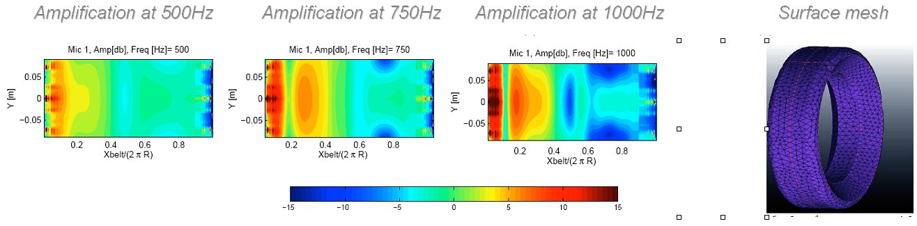
This is very important for some industrial problems. For example, at the contact between a car tyre and the road surface, there is a diverging space similar to a gramophone horn. This has the effect of amplifying any sound sources close to the road surface by up to 20dB. As the tyre surface is vibrating close to the road surface, this is extremely important to quantify and to take into account when trying to calculate the radiated far-field noise.
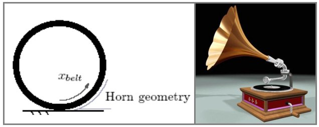
In order to determine this "horn amplification", a surface mesh of the tyre is created and an indirect boundary element calculation examines the sound radiation with and without the tyre geometry present. The difference between these is the amplification factor. If the tyre surface is unwrapped and laid out, the variation in amplification with position on the tyre surface can be mapped for a range of different frequencies. On the figure below, it can be seen that amplification up to 20dB occurs close to the contact patch with the ground at frequencies of importance in an A-weighting scale.
Once this "horn amplification" has been calculated with a standard sized tyre, it is possible to examine how this could vary if the tyre properties were varied, for example, by constraining the tyre modal shape in the centre of the tyre belt or with a change in curvature, radius or tread depth. The difference in the frequency of the radiated noise between a brand new tyre and one with a worn tread pattern is noticeable. <\p>
It is also possible to examine how the radiated noise changes when the tyre geometry is surrounded by shielding, for example, special wheel arch liners. These have variable damping material applied to the underside to absorb acoustic energy. However, as the peak horn amplification occurs very close to the road surface, they are limited in their effectiveness unless very close to the road surface, which leads to practical implementation problems.
An alternative method for reducing the acoustic radiated noise has been trialled in many countries, creating a road surface which is made of a more absorptive surface, for example rubber, or a porous surface, where the holes act as miniature Helmholtz resonators. By changing the impedance of the road surface, the reduction in sound pressure can be estimated. Although it can be shown that the noise reductions of these road surfaces are impressive, they are more costly and do not last as long as traditional solid asphalt or concrete surfaces.
Environmental noise pollution
The sound which is generated by car tyres rolling on a road surface is the largest contributor to the exterior noise from a car once it is travelling over approximately 35mph. The vehicle developments over the past few decades have led to a reduction in engine noise, exhaust and fan noise, however, partly as a result of the increase in tyre dimensions, the tyre / road interaction noise has increased.
In order to understand the generation of noise from rolling tyres, it is necessary to numerically model the tyre in order to understand the physical wave propagation mechanisms occurring inside the different materials which make up a tyre. The tyre itself is a complex series of steel, fabric and rubber layers, which are bonded together to produce the overall tyre belt. The tread rubber is moulded to the outside of this tyre belt.
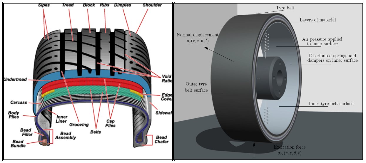
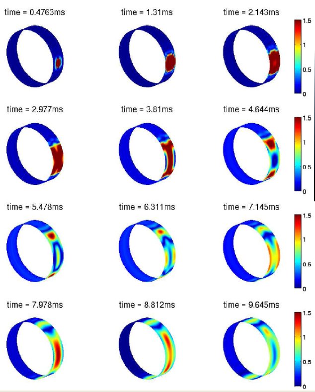
The wave propagation model used is an elasticity representation of the tyre belt, where each material layer is modelled in cylindrical coordinates. By applying boundary conditions from an air cavity, through these materials to the outside tread rubber, it is possible to obtain the natural frequencies of the tyre. Although the key interest is the vibration amplitude at certain frequencies, a Fourier inversion allows the waves to be seen as a function of time too.
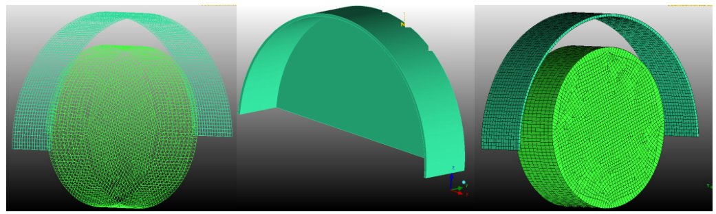
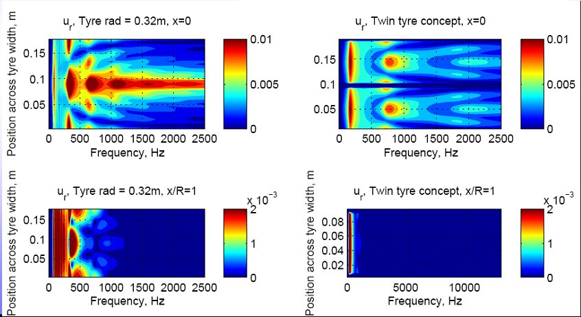
Once the physical wave propagation mechanisms are understood, it is possible to examine how the resonant frequencies of the tyre would change with an alteration of physical dimension, for example. This is shown below for a change in tyre width. The standard size tyre creates a significant amount of vibration in the region where environmental noise pollution is a problem, due to the application of an A-weighting scale.

For low noise tyres, it is possible to constrain the wavelength across the width of the tyre using reinforcing materials, in essence creating a high-pass filter on the tyre shape. This has the effect of moving the resonant frequencies higher up in the frequency range where the energy can be more easily dissipated as heat through viscoelastic damping. <\p>
To obtain the noise, it is necessary to take into account the acoustic amplification from the cylindrical geometry causing a diverging horn shape with the contact with the road surface, this is described above. In order to compute the horn amplification, CAD profiles of the tyre are produced and a commercial meshing program used to generate a smooth mesh over the surface.

Further information on the modelling on automotive tyres and the noise generated by the interaction when they roll on a road surface can be found by following this link.
Assistance with legal compliance issues
Information can be provided. Contact for information.